Latest products
Introduction to Cartridge Mechanical Seal (2)-
by:Lepu Seal
2021-03-12
Introduction to Cartridge Mechanical Seal (2)
2017-08-24
Introduction to Cartridge Mechanical Seal (2):
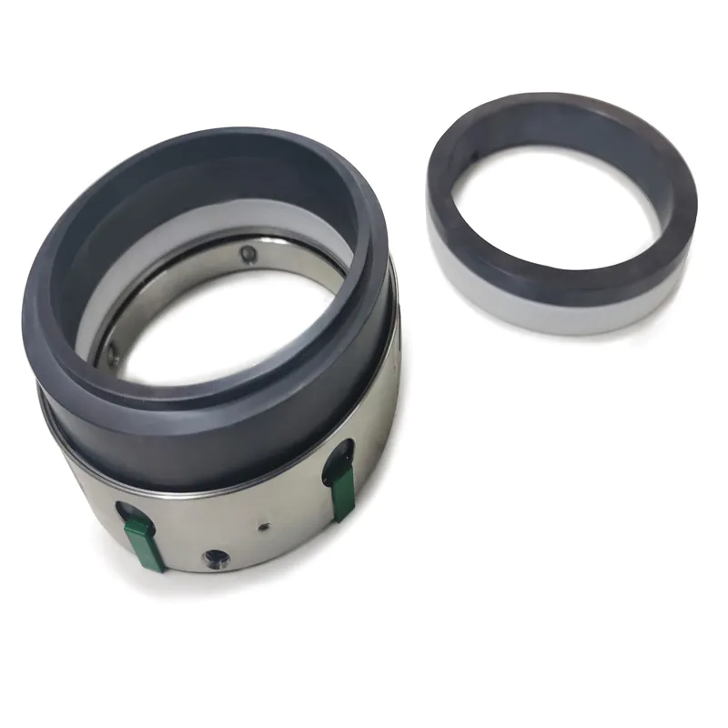
Shaft sleeves and glands are indispensable parts of cartridge mechanical seals, through which all mechanical seal parts can be combined. The gland can be connected with the body. When the temperature of the material is too high or too low and it needs to be washed, the gland can be processed to have flushing holes to meet the needs of the process. The set screw is also very important. It is the main part to overcome the friction between the dynamic and static rings. The head of the set screw of AIG318 has a spiral groove, which can prevent the screw and the shaft from slipping and loosening. 318i is a waist-shaped static ring gland with two gland bolts. The original sealing packing is used for sealing, and there is no need to modify the original equipment. When the mechanical seal needs to be flushed, you can choose 318A gland with flushing hole, which has four gland bolts, and meets the requirements of API standards.
The cartridge mechanical seal is assembled in the clean environment of the seal manufacturer. Skilled and correct combination can ensure the assembly quality; reasonable spring compression and rubber O-ring deformation can ensure the reliability of the seal; The overall air-tightness test is carried out before leaving the factory to further ensure the reliability of the seal.
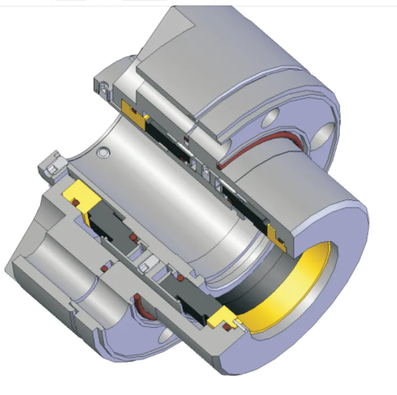
Figure 2-2 shows a cartridge mechanical seal with a rolling bearing. The placement of the bearing can effectively control the radial runout and movement of the shaft. It also provides a good working environment for the mechanical seal and makes the mechanical seal stable. Reliable operation. The features of this mechanical seal are: In order to facilitate the assembly and disassembly of the bearing, a bearing sleeve 4 is added, the outer ring 4 of the bearing is limited by the snap ring 5, the inner seat is positioned by the fixed ring 3, and the gland 1 has an oil injection hole, and Equipped with oil seal ring 2, which can be filled with grease regularly to lubricate the bearing.
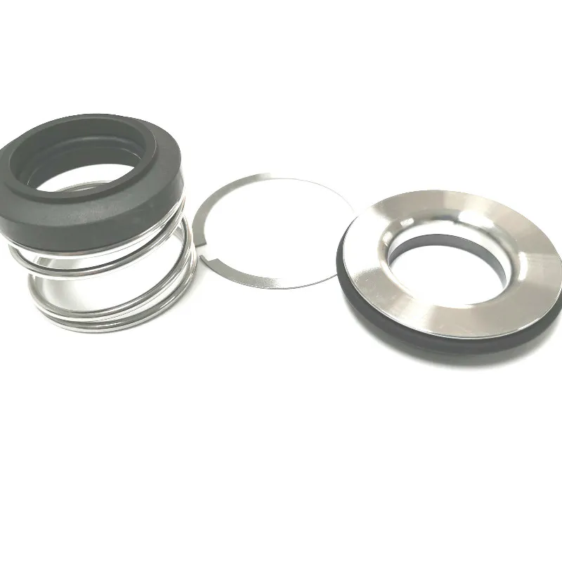
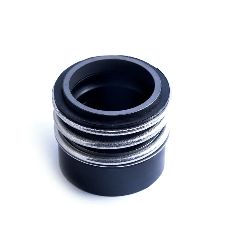
Figure 2-3 shows a single spring cartridge mechanical seal structure. Compared with a multi-spring structure mechanical seal, when the axial displacement of the shaft is large, there will be no obvious effect on the spring force, which can be effectively avoided. The shortcomings of large changes in spring force, this structure can be used in some occasions. The characteristic of the single spring cartridge mechanical seal is that the axial dimension is longer than that of 318i and 318A, but it complies with the installation requirements in GB/T6556-1994 'Types, main dimensions, materials and identification marks of mechanical seals'.
Figure 2-2318B Cartridge mechanical seal with rolling bearing
Figure 2-3318S single spring cartridge mechanical seal
Figure 2-42318 Double-end face cartridge mechanical seal
Figure 2-5 CHESTERTON155 mechanical seal
Figure 2-4 shows a double-end cartridge mechanical seal, which is composed of two sets of single-end mechanical seals. A liquid separating ring is installed between the two sets of mechanical seals to allow people to clean the sealing liquid to prevent the leakage of materials on the inner end surface and the lubrication of the outer end surface. The feature of this mechanical seal is that it is composed of two sets of single end faces and the shaft sleeve is longer, which brings some difficulties to processing.
Figure 2-5 shows the CHESTERTON 155 mechanical seal from Chesterton. The moving ring of type 155 is an integral hard ring, driven by the key groove on the shaft sleeve; the static ring is an integral soft ring, and the spring is installed at the tail of the static ring, so it is a static type. The static ring is a compensation ring with anti-rotation pins to prevent it from rotating. The positioning belt is wrapped around the shaft sleeve to control the compression of the spring. The gland of this model is very characteristic. There are eight rotating fins positioned on the eight sides of the seat assembly with top springs and snap rings. A gland nut can be placed in a group of two fins. Within the size range, four or less gland oyster nails with different diameters can be placed.
The cartridge mechanical seals introduced above all meet the requirements of GB/76556-1994. Since the radial size specified in the standard must include the shaft sleeve, spring, moving ring and other parts, the size of the spring is subject to certain restrictions, that is, the outer diameter of the spring cannot be too large, which will produce a larger spring winding ratio (spring diameter /Wire diameter), the spring processing requirements are relatively high, and a certain amount of permanent deformation is prone to occur.
The cartridge mechanical seal is easy to be accepted by users due to its simple installation. The spring compression, the width of the sealing surface, the balance ratio, the pairing of the dynamic and static rings, the interference of the O-ring seal, etc., are all the results of the accumulation of long-term experience and user feedback. The future development direction of mechanical seals is to ensure the most reasonable parameters of cartridge mechanical seals, unmanned installation errors, no spring clogging, no O-ring wear, etc.
Philips Cartridge Mechanical Seal Metal Bellows Cartridge Mechanical Seal 59u John Crane Single End Face Cartridge Mechanical Seal 559.html,
Introduction to Cartridge Mechanical Seal (1) Introduction to Split Mechanical Seal
2017-08-24
Introduction to Cartridge Mechanical Seal (2):
Shaft sleeves and glands are indispensable parts of cartridge mechanical seals, through which all mechanical seal parts can be combined. The gland can be connected with the body. When the temperature of the material is too high or too low and it needs to be washed, the gland can be processed to have flushing holes to meet the needs of the process. The set screw is also very important. It is the main part to overcome the friction between the dynamic and static rings. The head of the set screw of AIG318 has a spiral groove, which can prevent the screw and the shaft from slipping and loosening. 318i is a waist-shaped static ring gland with two gland bolts. The original sealing packing is used for sealing, and there is no need to modify the original equipment. When the mechanical seal needs to be flushed, you can choose 318A gland with flushing hole, which has four gland bolts, and meets the requirements of API standards.
The cartridge mechanical seal is assembled in the clean environment of the seal manufacturer. Skilled and correct combination can ensure the assembly quality; reasonable spring compression and rubber O-ring deformation can ensure the reliability of the seal; The overall air-tightness test is carried out before leaving the factory to further ensure the reliability of the seal.
Figure 2-2 shows a cartridge mechanical seal with a rolling bearing. The placement of the bearing can effectively control the radial runout and movement of the shaft. It also provides a good working environment for the mechanical seal and makes the mechanical seal stable. Reliable operation. The features of this mechanical seal are: In order to facilitate the assembly and disassembly of the bearing, a bearing sleeve 4 is added, the outer ring 4 of the bearing is limited by the snap ring 5, the inner seat is positioned by the fixed ring 3, and the gland 1 has an oil injection hole, and Equipped with oil seal ring 2, which can be filled with grease regularly to lubricate the bearing.
Figure 2-3 shows a single spring cartridge mechanical seal structure. Compared with a multi-spring structure mechanical seal, when the axial displacement of the shaft is large, there will be no obvious effect on the spring force, which can be effectively avoided. The shortcomings of large changes in spring force, this structure can be used in some occasions. The characteristic of the single spring cartridge mechanical seal is that the axial dimension is longer than that of 318i and 318A, but it complies with the installation requirements in GB/T6556-1994 'Types, main dimensions, materials and identification marks of mechanical seals'.
Figure 2-2318B Cartridge mechanical seal with rolling bearing
Figure 2-3318S single spring cartridge mechanical seal
Figure 2-42318 Double-end face cartridge mechanical seal
Figure 2-5 CHESTERTON155 mechanical seal
Figure 2-4 shows a double-end cartridge mechanical seal, which is composed of two sets of single-end mechanical seals. A liquid separating ring is installed between the two sets of mechanical seals to allow people to clean the sealing liquid to prevent the leakage of materials on the inner end surface and the lubrication of the outer end surface. The feature of this mechanical seal is that it is composed of two sets of single end faces and the shaft sleeve is longer, which brings some difficulties to processing.
Figure 2-5 shows the CHESTERTON 155 mechanical seal from Chesterton. The moving ring of type 155 is an integral hard ring, driven by the key groove on the shaft sleeve; the static ring is an integral soft ring, and the spring is installed at the tail of the static ring, so it is a static type. The static ring is a compensation ring with anti-rotation pins to prevent it from rotating. The positioning belt is wrapped around the shaft sleeve to control the compression of the spring. The gland of this model is very characteristic. There are eight rotating fins positioned on the eight sides of the seat assembly with top springs and snap rings. A gland nut can be placed in a group of two fins. Within the size range, four or less gland oyster nails with different diameters can be placed.
The cartridge mechanical seals introduced above all meet the requirements of GB/76556-1994. Since the radial size specified in the standard must include the shaft sleeve, spring, moving ring and other parts, the size of the spring is subject to certain restrictions, that is, the outer diameter of the spring cannot be too large, which will produce a larger spring winding ratio (spring diameter /Wire diameter), the spring processing requirements are relatively high, and a certain amount of permanent deformation is prone to occur.
The cartridge mechanical seal is easy to be accepted by users due to its simple installation. The spring compression, the width of the sealing surface, the balance ratio, the pairing of the dynamic and static rings, the interference of the O-ring seal, etc., are all the results of the accumulation of long-term experience and user feedback. The future development direction of mechanical seals is to ensure the most reasonable parameters of cartridge mechanical seals, unmanned installation errors, no spring clogging, no O-ring wear, etc.
Philips Cartridge Mechanical Seal Metal Bellows Cartridge Mechanical Seal 59u John Crane Single End Face Cartridge Mechanical Seal 559.html,
Introduction to Cartridge Mechanical Seal (1) Introduction to Split Mechanical Seal
Custom message